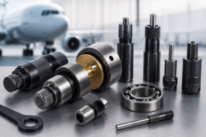



A bearing that moves in its housing stops doing its job. It can walk out of the bore, fret against the housing, load a neighboring part it was never meant to touch or release debris into an engine or airframe. Retention is the design decision that prevents all of this, and in aerospace it is rarely an afterthought. The method is set early, written into the drawing and then carried through manufacturing and every maintenance event that follows.
This guide looks at aerospace bearing retention methods from the engineer’s side: which methods are common, what drives the choice and how manufacturing and MRO change the picture. If you need a direct process comparison between the two forming methods, read Bearing Staking vs. Swaging: Aerospace Applications. This article focuses on the selection criteria around them.
Why Bearing Retention Is Critical in Aerospace Assemblies
Aerospace bearings work under vibration, temperature swings and reversing loads, often in assemblies that cannot be inspected between scheduled checks. A retention method has to hold the bearing against the axial loads it will see in service, and it has to do so for the full interval the maintenance program assumes.
Retention also affects how the component is repaired. A method that is easy to install but damages the housing on removal can shorten the life of an expensive part. A method that is simple to remove but needs extra hardware adds weight and parts count. The right choice balances holding strength, weight, installation control and repairability for the specific assembly.
Common Bearing Retention Methods
Most aerospace designs use one method or a combination of the methods below. Each relies on a different mechanism, so each places different demands on the bearing, the housing and the tooling.
Interference fit
The bearing outer ring is pressed into a bore slightly smaller than its outside diameter. Friction from the fit resists movement. Interference fits are common as a base condition, but they are sensitive to temperature, housing material and bore tolerance, and many aerospace designs add a positive retention feature on top of them.
Bearing staking
Bearing staking displaces housing material over the bearing’s outer ring chamfer, either at points around the circumference or as a continuous ring. The housing does the holding. Staking works with bearings that have no swaging groove, and the result depends on housing material and the staking tool profile. Aero Staking’s Staking Tools are designed for this operation.
Bearing swaging
Bearing swaging forms a lip on the bearing’s grooved outer ring outward onto a chamfer in the housing. Here the bearing does the holding. Swaging is widely used for rod end and spherical bearings with swageable outer rings, and it is often performed with tri-roller tooling. The guide How Does the Bearing Swaging Process Work? explains the sequence.
Retaining rings, shoulders and threaded retainers
Mechanical retention uses a shoulder in the housing combined with a retaining ring, a retainer plate or a lock nut. These methods add parts but allow removal without deforming the bearing or the housing. Lock nuts are tightened with dedicated wrenches such as the Spanner Wrenches & Lock Nuts Aero Staking offers.
How Assembly Design Influences Retention Method Selection
The design of the assembly narrows the choice before any tooling decision is made. Bearing type comes first: a swaging method requires a bearing with a swaging groove, while staking requires a housing with enough material and the right geometry around the bore.
Load path comes next. An assembly that carries significant axial load in both directions needs a method that resists both, which can mean swaging both faces or combining a shoulder with a second feature. Envelope and access matter too. Some assemblies leave no room for a retaining ring groove or a nut, which pushes the design toward forming methods. Others are positioned where a forming tool cannot reach after assembly, which influences both the method and the tool configuration.
Material Compatibility and Housing Considerations
Bearing housing design sets the limits for every forming method. The housing material controls how it responds to staking and how its chamfer supports a swaged lip. Aluminum, steel and titanium housings behave differently under the same tool, and composite or thin-walled structures can need low-force approaches to avoid damage.
Chamfer geometry deserves special attention. For swaging, the chamfer is the surface the lip forms against, so its angle, size and condition directly affect retention. For staking, the material near the bore edge is what gets displaced. In both cases the drawing defines the geometry, and in repair work the chamfer’s condition after removal often determines whether the housing can receive another bearing.
Manufacturing vs MRO Retention Requirements
In manufacturing, the retention method is installed on new parts under controlled conditions. Priorities include repeatability across many parts, cycle time, operator consistency and documented verification. Fixed equipment such as a drill press setup often suits this environment because it offers stable alignment and repeatable feed.
MRO work starts with a part that already has a retained bearing. The first task is removing it without damaging the housing. Swaged bearings, for example, are typically removed by cutting away the formed lip, a task that Aero Staking’s Bearing Cutters address. The replacement then has to be installed to the same requirements as the original, often in a hangar or on a component that cannot easily move to a bench. Portable tooling and careful chamfer inspection become more important here. Repair documentation may also limit how many times a housing can be reworked, which is a factor worth reviewing before choosing or changing a method.
Comparison Table: Retention Methods and Engineering Considerations
The table summarizes how the common methods compare across the factors engineers usually review. It is a starting point for discussion, not a design rule. The applicable drawing, bearing specification and OEM documentation govern every final decision.
| Method | What holds the bearing | Bearing requirement | Housing considerations | Removal impact | Typical tooling |
|---|---|---|---|---|---|
| Interference fit | Friction from the fit | Standard outer ring | Bore tolerance and thermal behavior are critical | Press-out can mark the bore | Installation and removal tools |
| Staking | Displaced housing material | Outer ring chamfer | Enough material and suitable geometry at the bore edge | Staked material must be addressed on removal | Staking tools, anvils |
| Swaging | Formed lip on the bearing | Grooved, swageable outer ring | Chamfer geometry and condition define retention | Lip is cut away, chamfer must be inspected | Tri-roller swaging tools, cutters |
| Rings, shoulders, nuts | Mechanical stop | Compatible with the stop feature | Requires a groove, shoulder or thread | Removal without deformation | Ring tools, spanner wrenches |
Common Questions About Aerospace Bearing Retention
What is the most common bearing retention method in aerospace?
It depends on the component. Swaging is common for rod end and spherical bearings with swageable outer rings, staking appears in many housing designs and mechanical retention is used where removal without deformation matters. The bearing type and drawing decide the method.
Can I change the retention method during a repair?
Not on your own. The retention method is part of the approved design. Any change requires engineering approval and the applicable OEM or authority documentation.
How do I verify that a bearing is properly retained?
Verification usually combines visual inspection, dimensional checks, a rotation or torque check and an axial proof load test as defined by the procedure. Aero Staking’s Testing Tools support this stage.
Do staking and swaging need different tools?
Yes. Staking tools deform the housing, while swaging tools form the bearing’s lip. Each tool must match the bearing and housing geometry of the job.
What bearing retention requirements should I review before selecting tooling?
Review the bearing part number, the housing material and chamfer geometry, the axial load requirement, access around the assembly and the verification method. Those bearing retention requirements define which tooling can deliver a compliant result.
Conclusion: Matching Retention Methods to Application Requirements
Retention method selection is often treated as a single choice made on the drawing. In practice it is a commitment that follows the part through its entire service life. The method chosen today determines what an MRO technician will have to remove, inspect and reinstall years from now, and with which tools.
That is why it pays to evaluate retention with both ends of the life cycle in view: how the bearing goes in, how it comes out and what the housing looks like after each cycle. If your application requires forming tools, staking tools or tri-roller swaging tools, review Aero Staking’s Forming Tools and Tri-Roller Swaging Tool. For assemblies that standard equipment does not fit, explore Custom Tools or contact Aero Staking to discuss your requirements.